



Pneumatics · Flow & Check Valves
Flow Control Check Valves for Pneumatic Cylinders – Precise Speed Control
Flow control check valves regulate the travel speed of your pneumatic cylinders – defined, repeatable, and without interfering with system pressure. In one direction, the valve meters airflow via an adjustable needle; in the reverse direction, the integrated check valve opens for free flow. This allows you to set extension and retraction speed independently. At STASTO, choose from three body styles – inline, inline-threaded, and push-in swivel – with port sizes from M5 to G1/2.
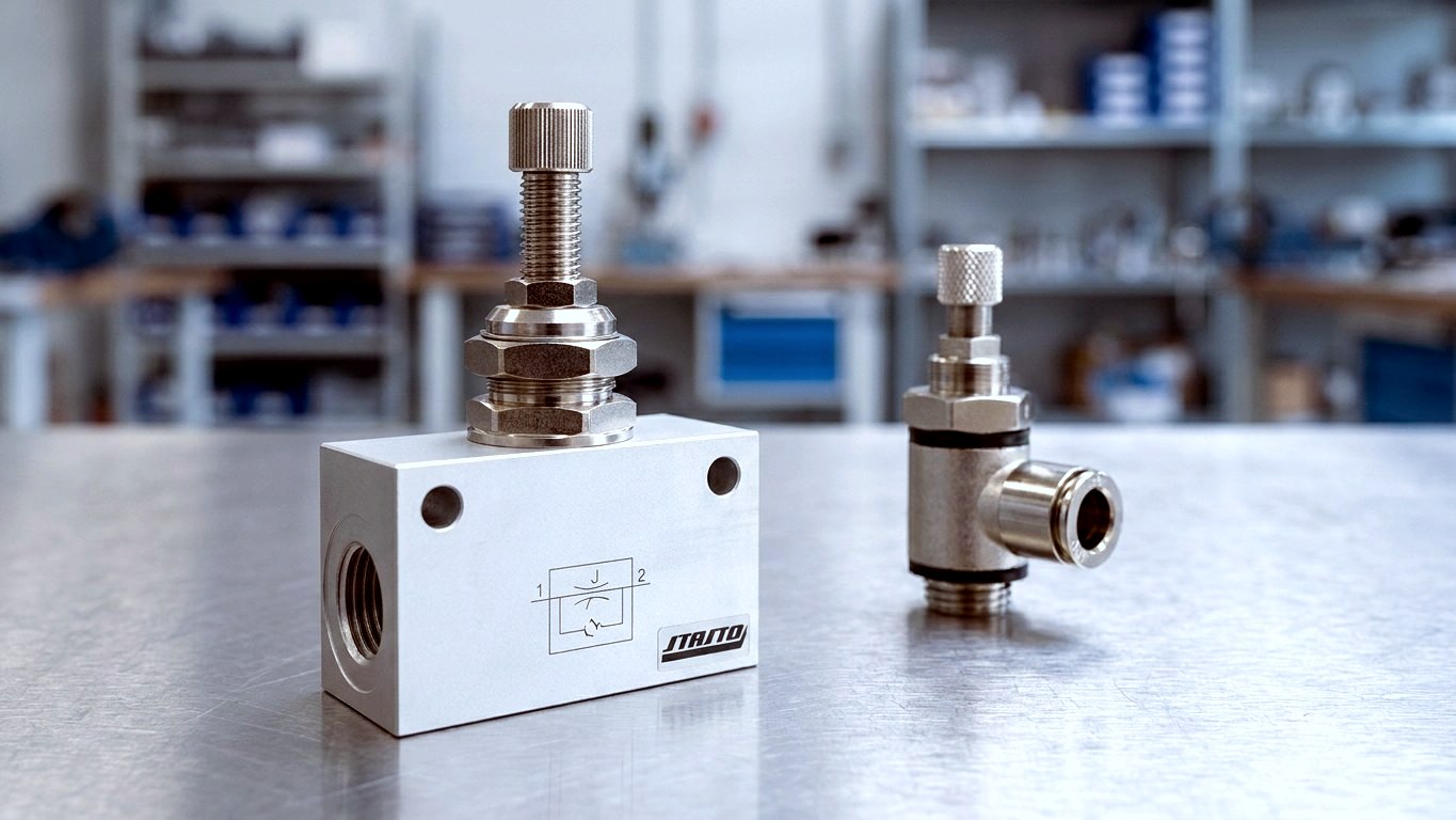
Inline · Threaded · Push-in
Advantages
Why Choose STASTO Flow Control Valves
Direction-dependent flow control for smooth, repeatable piston movement – matched to your cylinder, installation space and tubing layout.
Independent Speed Adjustment
Extension and retraction of the cylinder can be adjusted independently – typically via exhaust flow control for consistent movement.
Three Body Styles for Every Installation
Inline body (series MV21-U, MV34-U), screwed-in body (series MV44) and swivelling push-in versions (series UFC05-C/V, MV15MA35-C/V) cover port mounting, compact installation and flexible tubing routing.
Wide Range of Port Sizes
From M5 through G1/8, G1/4, G3/8 to G1/2; nominal flow rates vary by series and port size – for series MV21-U, for example, from 70 to 1,350 Nl/min.
Precise Fine Adjustment
Adjustment via slotted or knurled screw, with locking facility on selected series to prevent accidental changes – suitable for cylinders to ISO 15552 and ISO 6432.
Design Types
Flow Control Check Valves by Design Type
Select the right series based on cylinder port, available installation space, and tubing routing.
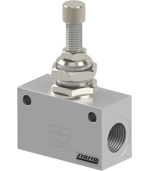
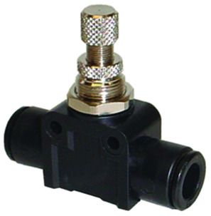
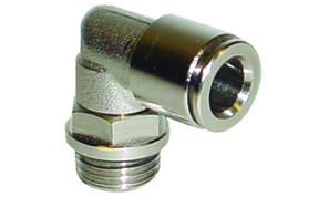
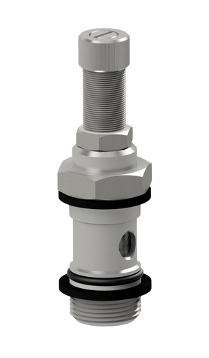
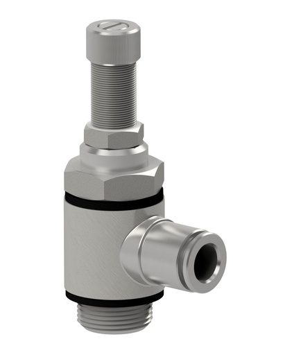
Design types compared
Block, Inline, or Swivel – which design type is right?
The three design type categories differ primarily in mounting method and tubing routing. An overview for quick pre-selection.
| Block | Inline (screwed) | Push-in (swivel) | |
|---|---|---|---|
| Series | MV21-U, MV34-U | MV44 | UFC05-C/V-W/-S/-F, MV15MA35-C/V |
| Mounting | Directly at cylinder port or in pipeline | Screwed into cylinder or component thread | Push-in fitting, swiveling |
| Connection | M5 to G1/2 (MV21-U), tubing 4–8 mm (MV34-U) | Threaded installation, space-saving | Push-in tube connection |
| Tube routing | Fixed at port | Compact at fitting | Flexible, adjustable |
| Typical application | Standard cylinders, general applications | Tight installation spaces | Flexible tubing, variable routing |
Guide
Meter-out or meter-in – which is right for you?
The choice of throttling direction determines the cylinder's movement behaviour. Follow these steps to find the right version for your application.
Understanding throttling direction
- Meter-out (exhaust throttling)
- The air exhausting from the cylinder is throttled. A back pressure builds up on the exhaust side – this air cushion results in smooth, consistent and more load-independent movement. The most commonly used method in practice.
- Meter-in (supply throttling)
- The incoming air supply is throttled. Used in special cases such as single-acting cylinders or very small volumes, but tends to cause jerky motion at higher loads.
- Nominal flow rate
- Indicates the range of adjustable flow rate – for the MV21-U series, for example, 70–1,350 Nl/min. Exact values can be found in the datasheet for each variant.
Selection in four steps
- 1. Determine cylinder port
- Specify thread (M5, G1/8 to G1/2) or push-in tubing connection.
- 2. Choose mounting style
- Block (port mounting), inline/screwed (compact) or swivel/push-in (flexible tubing routing).
- 3. Define tube O.D.
- Matched to your tubing – depending on the series, e.g. 4–16 mm.
- 4. Check throttling direction
- Meter-out (standard) or meter-in, depending on the series variant.
Applications
Where flow control valves are used
Wherever pneumatic cylinders need to be moved in a controlled and repeatable manner.
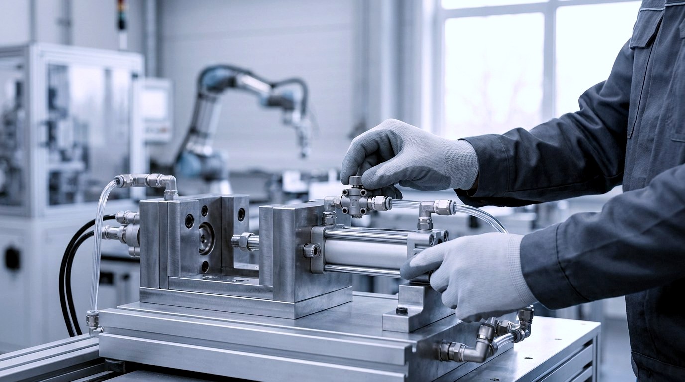
Setting cylinder speed
Control the extend and retract movement of pneumatic cylinders separately, e.g. for gentle closing of a clamping device.
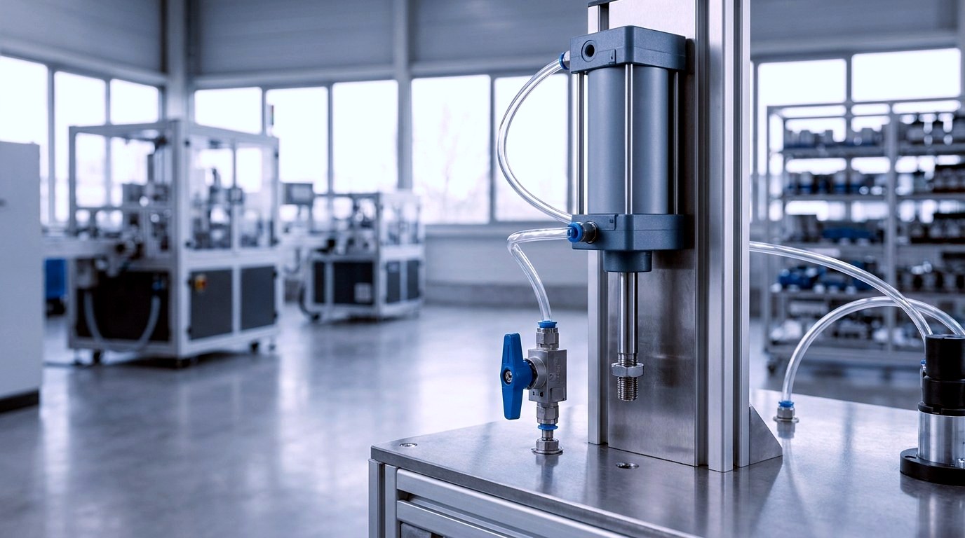
Exhaust throttling
Proven standard method: air is throttled on the exhaust side, creating a back-pressure cushion that keeps the piston running smoothly and evenly.
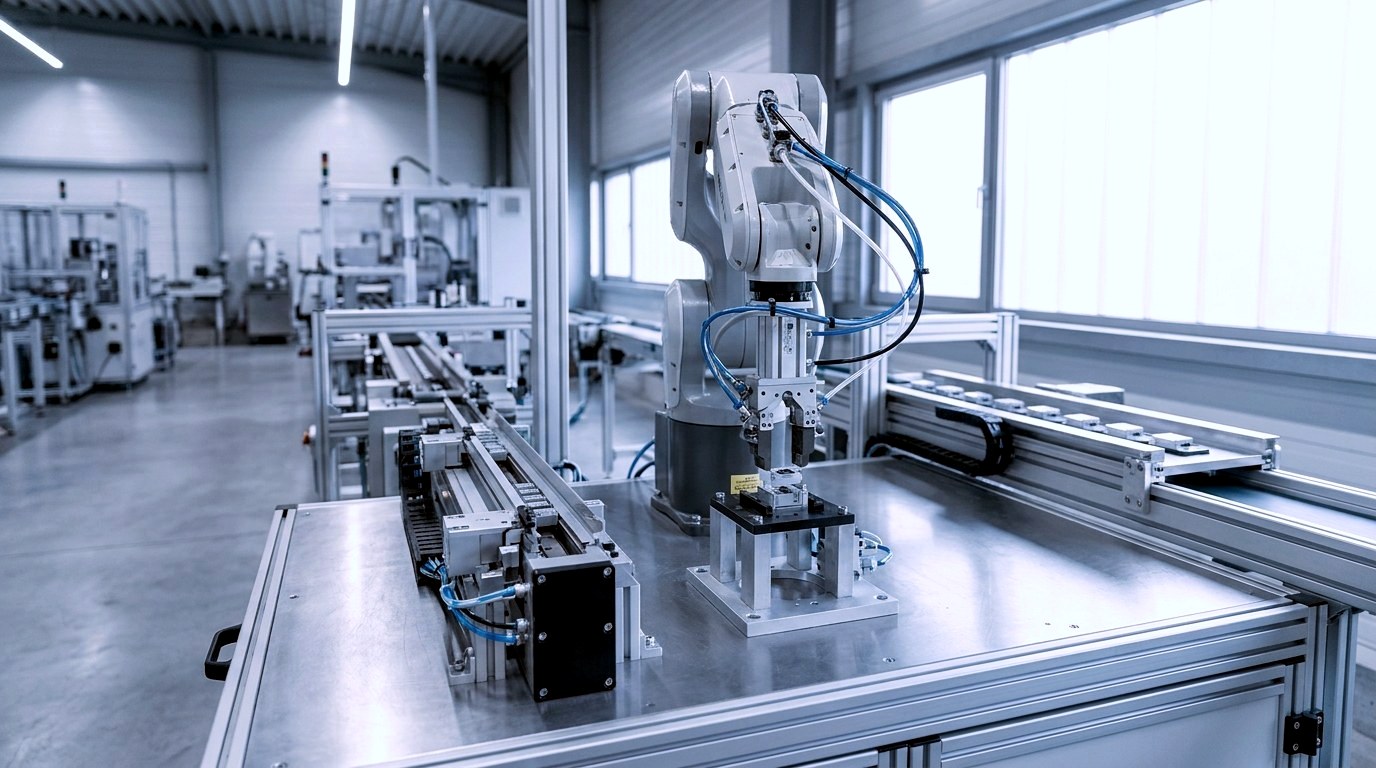
Handling and assembly technology
Controlled movements on grippers, feeds and slides in automated production lines.

Fine-tuning cycle times
Fine-tune motion sequences on existing cylinders and precisely adjust cycle times in systems.

Smooth motion in packaging
Smooth, jerk-free piston movement on cylinders in packaging and filling lines for gentle handling.
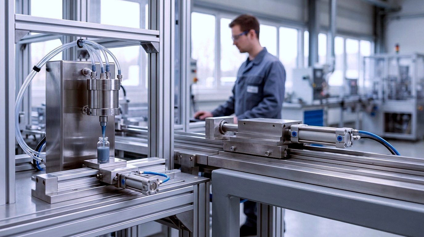
Dosing and Feed Motions
Controlled, repeatable cylinder movements on feeds and slides in process engineering systems.
Availability & Support
Selection, Variants and Support
Port size, tubing O.D., nominal flow rate and materials vary by series – exact specifications are listed on each product page.

Availability by Series
Order quantities and delivery information are available on the respective product or variant page.
Technical Data per Item
Port connection, tubing O.D., nominal flow rate and materials are listed in the datasheet for each variant. Temperature and pressure ranges vary by series.
Special Versions and Consultation
Questions about design, port connection or flow direction can be answered by our technical team on request.
Frequently Asked Questions
FAQs about flow control check valves
Answers on function, installation, connections and selection.
What is a flow control check valve and how does it work?
A flow control check valve combines an adjustable restrictor with a check valve to control the speed of a pneumatic cylinder in a direction-dependent manner. In one flow direction the airflow is throttled and regulated via a needle; in the reverse direction the check valve opens for free passage.
Where should I mount the valve – at the cylinder or in the tubing?
This depends on the body style: block and inline screw-in valves are preferably mounted directly at the cylinder port, while swivel/push-in valves allow flexible routing along the tubing run. Port mounting at the cylinder is the most common approach for exhaust throttling.
What is the difference from a plain flow control valve?
A plain flow control valve (e.g. Series MV21-B, MV34-B) throttles in both directions, whereas a flow control check valve throttles in one direction only. The flow control check valve allows air to pass freely in the reverse direction – which is the prerequisite for direction-dependent speed control.
What connections and tubing diameters are available?
Depending on the series, threaded connections range from M5 through G1/8, G1/4, G3/8 to G1/2; push-in tube connections are available in common diameters depending on the variant. Exact specifications can be found on the respective product page.
What flow rate range can I adjust?
The adjustable flow range depends on the rated flow of the series – for Series MV21-U, for example, from 70 Nl/min (M5) to 1,350 Nl/min (G1/2). Details for each variant can be found in the datasheet.
Which cylinders are supported?
The valves are suitable for common pneumatic cylinders, such as those to ISO 15552 or ISO 6432. Select the appropriate combination of port and body style to match your cylinder type; if in doubt, we are happy to advise you.
Related Products
Related Categories
Complementary components and related products for your pneumatic control system.
Select now
Find the right flow control check valve
Choose body style, connection type and tubing diameter – or let our technical team advise you.